 Namila Bandara
Project Nixie Display Clock - Info Gathering

1 Intro
Since my AL days, I wanted to build a Nixie display clock. As parts were so pricey and less knowledge about electronics I didn’t start it. So yesterday I stumbled upon a Nixie display clock while watching some youtube video. Since that, all I wanted is to build one. If you are interested in how a nixie tube is made, watch this video. This will be a long project as I’m going to build this in my free time. I hope to design and print a PCB. So let’s start it!
2 Parts Going to Use
After some info gathering, I decided to build this clock using Arduino nano as the microcontroller as it’s small and easy to program. Followings are the main parts I’m going to order for this project.
- 6x IN-12B Nixie tube
- 6x K155ID1 BCD to Decimal decoder
- 6̵0̵x̵ ̵M̵P̵S̵A̵4̵2̵ ̵N̵P̵N̵ ̵H̵i̵g̵h̵ ̵V̵o̵l̵t̵a̵g̵e̵ ̵T̵r̵a̵n̵s̵i̵s̵t̵o̵r̵
- 6̵x̵ ̵7̵4̵H̵C̵4̵2̵ ̵B̵C̵D̵ ̵t̵o̵ ̵D̵e̵c̵i̵m̵a̵l̵ ̵D̵e̵c̵o̵d̵e̵r̵
- 3x SN74HC595N Shift Register
- 1x Arduino Nano
- 1x 180V High Voltage DC boost power supply module
- 3x 74HC595 Serial-Parallel Shift registers
- 1x DS3231(or similar) Arduino modular Real-Time Clock(RTC)
3 The Plan
Here I’m planning to build a 6 digit nixie display clock. For this, I’m planning to use Arduino nano as the microcontroller. Follow shows the pinouts of Arduino nano. There is a total of 13 digital pins.
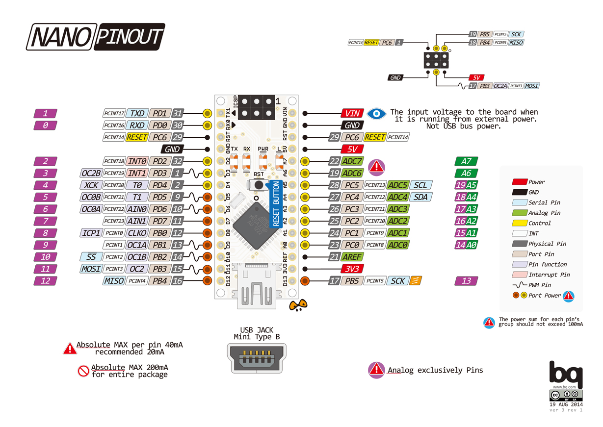
Arduino nano pinouts
I choose IN-12B nixie tubes for my projects is they are cheaper than the other nixie tubes and common on ebay.
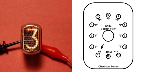
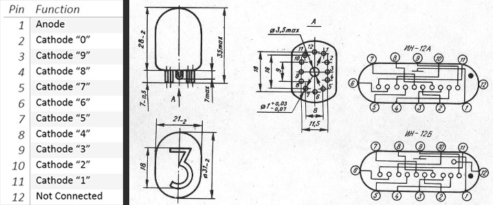
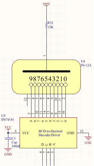
There are 12 pins available on IN12B (11 pins in IN12A), Pin 1 is the anode which sticks to 180V DC power and pin 2-11 are cathodes for relevant numbers. IN12B needs 180V to illuminate the numbers. This is why a 5v-12V to 180V High Voltage power supply module is used. A 15K resistor is used to limit the current (normally 2.5mA flows through the nixie tube).
IN12B Connection to BCD-Decimal Decoder
The next problem is as the nixie tube is operating at high voltage, Arduino nano or any microcontroller cant handle it. So it is needed to have some separate circuit/device to operate nixies using Arduino nano commands. K155ID1 BCD-Decimal decoder is going to used(Datasheet) Even the K155ID1 are high priced and old I googled for alternatives and found from stackexchange about the MPSA42 NPN high voltage transistor (Datasheet) which can work around 300V. To forward bias the transistor we need to provide 6V to the base and can get 300V Collector-Emitter(VCE) / Collector-Base (VCB). If Base current is more than 5mA it will kill the transistor, to protect it use relevant calculated resistors. This is ideal for a high voltage load using a micro-controller. Using 10x transistors for we can control 1 Nixie tube.
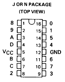
K155ID1 Pinout
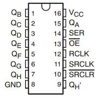
SN74HC595N Pinout
Now there is a new problem. We needed to use 10 pins to control those Base pin on each transistor, and we are using an Arduino Nano and I got only 13 digital pins. So how to do it? :/ To solve that issue I’m planning to use 74HC42 BCD-Decimal decoder (Datasheet). By using 1 decoder I can control a 1 nixie tube. Cool right. If you look at the pinout it needed 4 inputs to control the 11 outputs. Total of 24 inputs needed to control all the 6 nixie tubes. So again another problem. To solve this I can use SN74HC595N 8bit shift register (Datasheet). By using 3 shift registers I can get 6x4bit outputs with using 3 inputs from the microcontroller. Easy right?
Edit
I found another replacement for K155ID1 decoder, HV5530 32-Channel Serial-to-Parallel Converter (Datasheet). Using a single IC we can control 2 nixie tube. Since one unit cost nearly $7-$9 this won’t work :(. So I decided to go back to K155ID1 decoder, as it will be easier to work rather than tons on transistors in the board. So no more transistor and 74HC54 decoder.
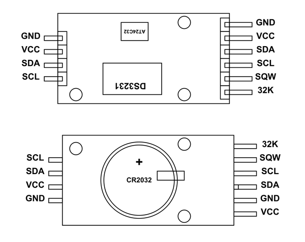
DS3231-RTC-Pinout
Now the last device, DS3231 RTC module (Datasheet) is consist of a battery where we can save the time even the clock is powered off.
4 Final Thoughts
Now all I have to do first is to order relevant parts from the eBay and wait for them. Till that time I hope to start designing the circuit diagrams. All the details about this project will be updated through my blog. There may be errors what I suggested in the post as I did a quick research in a few hours and wrote this post. If you found any please be kind to inform me about them using the comment section. Also, share your thoughts, improvements about this project. I referred projects done on Instructables and Hackday . Keep in touch. ;-)